Abstract
Our
project is a line following robot which follows a black line on a white
surface. It uses eight sensor arrays which detects the presence of light. The
sensor output is then feedback to the comparator which takes two inputs and
outputs of binary 0’s and 1’s. The binary codes from the comparator is then
inputted to the microcontroller which is programmed and sends signals to the
motor driver which controls the two DC motors to go forward, backward and stop.
In addition, we also programmed the robot to control the speed of the two
motors using Pulse Width Modulation (PWM). To limit the oscillation of the
robot and to follow the line in smooth and straighter motion, we also add in a
Proportional Integrator Derivative (PID) control to our robot.
Introduction
Our main objective of
this course is to design and implement a robot that can detect a line visible
on the ground and simultaneously move and follow it. Materials for this type of
project are readily available to us. These kinds of designs are often used in
modern systems, perhaps not all in the same manner. Proximity and light
detection are utilized in many control systems, for example auto-parallel
parking or self-brightening/dimming lights. The field of robotics has grown
from the needs and imaginations from individuals. Though there are endless
kinds of control systems, our focus is the basic principle of an autonomous
system that takes an input from the various sensors and outputs the desired
driving motion.
Methods
Sensors
For
our sensors, we used a pair of infrared (IR) light emitting diodes (LED) and
phototransistor diodes. It is in array of eight paired sensors which is placed
in a protoboard, 1 centimeter apart and evenly spaced for accuracy. The IR LED
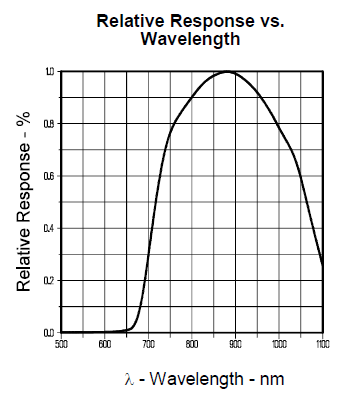
produces infrared lights at peak emission of 890 nm wavelength and the
photodiode has a peak response of about 890 nm (as seen in figure 1).
Figure
1:
For our robot, the sensitivity of detection is very
important. Therefore, having the right pair of LEDs is one of the important aspects
of building and choosing the right component for the robot. Another aspect for
detection is how far away the distance of the light rays when it leaves from
the IR LED to the tip of the photodiodes. The distance between these two lens
tips is approximately 0.5 inches.
Figure
2:

As seen in figure 2, the relative output current is
about 0.55 mA of the distance of 0.5 inches. By limiting or decreasing this
distance, it will give the robot more accurate readings and higher output
currents to be feedback to the comparator.
The way the photodiodes works is that its resistance
decreases when detecting IR light which give a high output voltage. An ideal
sensor has a near zero resistance in presence of light and a very large
resistance in absence of light. A simple schematic diagram of a pair of sensors
is seen in figure 3.
Figure
3. Schematic diagram of a pair of sensors

Comparator
The
signal from the output voltage of the phototransistor is an analog signal. To
communicate with the microcontroller, the robot needs something to convert the
signal to digital. For this design, we used an LM324 comparator. This IC is
essentially four operational amplifiers on one device. We need a total of two
of these IC’s to supply one op-amp per sensor pair (total of eight). For the
input voltage to the ‘ – ‘ terminals in the op-amp, we connected a
potentiometer to vary the resistance required. This gives us the capability of
tuning the resistance to the appropriate amount, thus giving the proper gain.
When adjusting the sensors, we see that there is a clear line that transitions
from fully on to fully off. Somewhere in this region there is a finer line that
we need to have the sensors react to our environment correctly. The robot will
not detect the black line until the potentiometer is adjusted to this point.
Microcontroller
A
simple line following robot could be built with purely analog components in
which case it wouldn’t need a microcontroller. However, we needed a system that
allows us to implement PID control. For this project, we chose the Atmega16
microcontroller. This is a 40 pin programmable IC with onboard memory. We chose
this device because we’ve had experience in microcontroller design using the
same device. To program the chip, we used the STK200 development kit. This
comes with the JTAG Ice which we need to connect the board to our computers.
The software AVR Studios, which is included, is used to write and transfer the
program to the controller. The IC is divided into 4 ports which we assigned to
the sensor array, programmer, motor driver, and the LCD.
Motor
Driver
In
order to dictate the speed and direction of our robot, we need a motor driver.
We chose the L293D as this is commonly used for these types of projects. It
also satisfies the rated current of the DC motors. The L293D is also an IC
which operates as logic AND gates. There are four input pins which are paired
with the enable pins. One chip can control two motors independently. The
operational diagram is show in figure 5.
Figure
5. Motor driver diagram

As
you can see from the diagram, the pins 1 and 2 alternate between high and low
which affect the direction of the current and consequently the motor’s
direction.
Motor
Hobby
DC motors generally have low torque and high rpm’s. But for our design, we
needed lower rpm’s and more torque. There are geared motors which meet our
requirements. These appear as standard dc motors with a larger casing. This
casing contains a series of gears which lower the output rpm and increases
torque. The motor we chose had a peak rpm of 190 and a minimum 9V. The normal
operating speed is determined by how much voltage is supplied to these motors.
Initially we used a standard 9V battery for testing. This was apparently too
slow for our needs so we raised the power supply to 12V.
Mechanical
Design
There
were a few requirements for the chassis of the robot. Even though the motors
were capable of supporting all the parts, weight is always a factor when it
comes to speed; the chassis should be lightweight. The sensors had to be
shrouded on the sides in order to block out light disturbances; normal room
lighting can be detected by the IR sensors. The center of mass needed to be as
close to the ground as possible, so the parts should be placed lower,
especially the batteries. This would allow the robot to make quick turns with
less effort.
Due
to uncontrollable circumstances, we couldn’t get the design for the chassis of
the robot. To complete the robot, we simply needed an enclosure that can secure
all these parts together. We used a simple project enclosure with the
dimensions 3 x 5 x 6.5 in. The sensor board needed to be placed as far from the
motors as possible to compensate for any delay in the electronics. The general
layout can be seen in figure 6.
Figure
6. Chassis & parts layout

Conclusion
After
completing the project, there were a number of problems we needed to address.
The most critical issue is that only one of the two motors can change its speed
and direction. This resulted in a robot that can only turn left. To be able to
demonstrate that the robot is still capable of detection and correction, we
used a closed oval circuit and positioned the robot to travel counterclockwise.
Another problem we encountered was the adjustment of the potentiometer. As
discussed previously, the potentiometer needed to be very precise in order for
the sensors to react to the black line correctly. This was very time consuming
and needed to be done often after operation since the rapid movement of the
robot changes the position of the dial.
There
were many design tradeoffs that we made in this project. Budget was limited as
well as time. Many factors contributed to the choices of parts and design
procedures. But the worst tradeoff was the protoboard and wiring procedure. We
chose the protoboard because it was readily available and gave us flexibility
in design. However this was the most time consuming part of the construction of
the robot. Also, it was a cause of many errors which we found through
troubleshooting. The chance of short circuiting during soldering was high. In
retrospect, we should have ordered a PCB earlier so we don’t have to worry
about wiring the main board and sensor board.
Videos
Testing the sensor response:
First Test:
More Test:
Final Product:
No comments:
Post a Comment